


|
*New* Follow the restoration of my Fli S2 Lambro, as it happens!
This is an on going project so feel free to check back from time to time. I started this in August 2004, my aim is to finish it in 11 months in time for Isle of Wight 2005. While that may sound a long time, I have a wife and three kids that like to spend our money faster then I can earn it! My youngest is 4 years old, so by the time he goes to bed, I dont have much time either :-)
Work was last carried out on the Lambro on 24/11/04, this page was updated the same day.
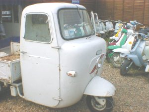 |
I began the "restoration", in early August, 2004, after a year or so of not giving my Lambro enough use or attention, I decided it was time to look after the "truck" At first I was going to do a simple resotration, pait the cab, the doors and have the rear pick up bed repaired. As I got further and further into the work, as you always do, the descision was taken to go "all the way". |
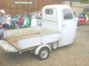 |
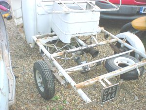
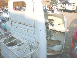
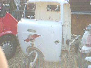
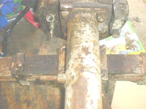
This and the picture above show the condition of my Lambro, pre resotoration. My Lambro was brought in via a dealer in Italy, and purchased from the UK dealer that brought it from them! Before this the Lambro belonged to a local council in Italy, it was used to clear and keep the local parks and greens clear. It at one time in its life been blown over, with a slightly lighter shade of grey then it should have be, presummably by the council. I have seen the destinctive red stripe on the front and side a few times before, so can only presume it is the councils colour scheme. |
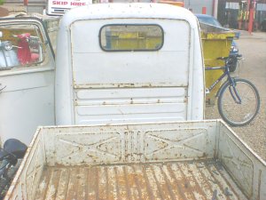 |
As well as the respray, at some point the Lambro had the rear canvas fold down back taken out and replaced with a sheet metal plate, with window. Apart from its age, and some of the spot welding allowing the outer part of the plate to start to crack the paint, the plate has been pretty well made and fitted quite well. Their is a support frame for the window, so I will be leaving this in place as it makes the hole cab more secure. |
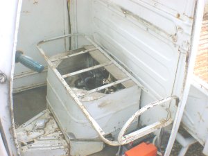 |
A local upholsterer came over and saw my Lambro, we got chatting and eventually he agreed to re trim the bench seat and back rest pad, so out it came quickly to be given to him. By the time I had found my camera, I realised I had forgotten to take photos of what the seat looked like. Oh well, its a black vynil bench seat and pad, what more do I need to know when rebuilding! |
 |
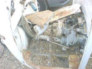
With the seat pad gone, time to take out the seat frame, as this could be recieving repair if it needed it. Two small dents were removed so the seat frame is all ready for blasting and painting. Back to the strip, the rear pick up bed looks very solid, plenty of Italian rust, but no rot. Time to take this off. It is secured by six bolts, as you can imagine, water, salt, the leaves from the park in Italy all have taken their toll on the bolts. Five came out, but despite all the WD40, heat, and gentle force given, the sixth one snapped! No problem, drill this out, and re tap the thread. |
 |
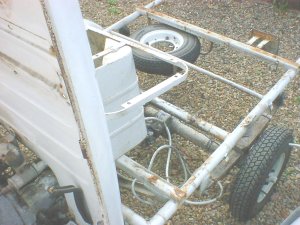
With the rear box off, and taken over the other side of the yard for a small amount of repair work, it was soon evedent more major work is needed. The rear strut under neath, holds the tailgate hinges, but is rotten. This and quite a bit of rust is making me see if I can source a van body from somewhere before I embark on some major repair work, we will come back to this at a later stage!
Next up was taking the two rear mudguards off, they are held on by three bolts each, the number plate and holder, then rear lights were taken off and the wiring loom unplugged and taken back towards the carb. With this all out the way, I can easily get to the brake lines, cables, and rear suspension when the time comes to strip these. I did not take them off first, so if need be I can still move the truck around easily on all its wheels. |
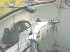 |
Time to turn my attention to the cab, and all the insides, this is where the hard bit begins! Four windows need to be taken out, so I enlist the help of a friend, who is an independant windscreen fitter. I would say a replacement windscreen for a 1962 Fli is not the easiest thing to find in the world, so I took no chances in having a go myself. As things go, I was on the phone for about 30 seconds to a minute, when finished I run outside to help John (the windscreen man) only to find front and rear windows already out, not only that he is on his phone sourching new surround rubbers, top bloke!
Also on the dash board, you can see the windscreen washer bag, even though from new these early Lambro's never hand windscreen washers, when I took mine for MOT, they failed it and made me fit them! |
 |
With the screens out, time to take the doors off. Doors were an option on the earlier models, so finding these can be quite hard as there are quite a few different types just to make life harder as well. |
 |
Next out come all the floor pans, two either side were a real pig to come out. Just about every bolt had to be drilled. As the chassis has captive nuts to hold most of the flooring in, so the last thing I wanted to be doing is grinding all these off and rewelding new ones on. To get the floor pans off, I drilled each bolt with a 1mm drill bit, and gradually got bigger until they came out. The centre belly ban and centre floor trim came out quite easily compared to the two main sides. |
 |
Once all the floor pans came out, it leaves you able to get to the engine, brake cylinder and pipes, cables and wiring loom. Bit by bit the Lambro was taken apart, parts sorted out and placed in boxes of parts needing painting, plating etc etc, or parts just needing my time attention and restoring by what ever means I have. With the Lambro stripped of all its parts, bar the cab and wheels, as I had the wheels re painted about a year ago I wasnt planning to re do these again. How ever after peeling back some of the older |
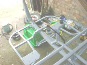 |
After taking off the cab, forks, wheels and rear axle, I had to move the parts out the way, so no photos were got of these. Not to worry after the frame came back from being sand blasted and powder coated, I took a picture or two so you can see the bare frame. After all a picture of a dirty olf frame is not really what you call exciting, well neither is this really but at least you can see how the "tubing" is done. The front part looks very like a Lambretta, fork tube is pretty much identical bar a few mounting points for the master cylinder, hand brake, reverse gear chage etc. |
 |
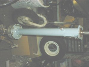
While waiting for other parts to return, time can be devoted to the mechanical side of things. The rear axle and leaf suspension were taken out as one unit, and then stripped accordingly. First is the rear axle, stripped of leaf springs, rear hubs and brake plates. As the rear axle contains so much grease, oil and pinions gears, total strip, blast and paint would be time consuming and expensive. |
 |
Stripping the rear leaf suspension, is not to hard a job to carry out. The frnt and rear are held in with what looks like front fork bolts from a Lambretta scooter, at the front there is one per side, at the rear, two, these fit through a bracket that attaches the leaf to the frame, instead of direct like the front. One these six bolts are out and you have discouncted the drive shaft and brakes, the axle and suspension can be taken out as one unit. The last part to take off are four nuts each side from U shaped bolts, these then allows the leaf spring set as a hole to come off the axle. |
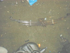 |
With the leaf suspension off as one unit, I decided against splitting the leaf springs, as this can cause handling problems if you do not get the leaf springs bac in the same position. The leaf springs were sanded and blasted by hand as much as possible ready for painitng. After checking as many leaflets, books and pictures as I could, it appeared the leaf springs came in black, so five or six of black paint were applied. After the paint has been allowed to dry for a few weeks, and I am happy with the application of the paint, the leaf springs will be soaked in oil to eleviate any squeaks you could get! |
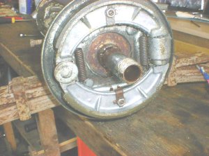 |
Time to turn my attention to the rear brakes. All braking components were replaced about two years ago when they recieved a major overhaul, so all that is needed is to re strip the hub, and back plate to prepare the back plate for painitng. The brake shoes are held on by two springs, the shoes also have a stud and locking mechanism to level themselves up. Undo both of these, ease the shoe off over the wheel cylinder and off they come. It appears to have a slight leak, so I shall soak the shoes in parafin, set light to them to burn any oil or brake fluid off, thne rough them up with sand paper and they will be fit for another good few years service. |
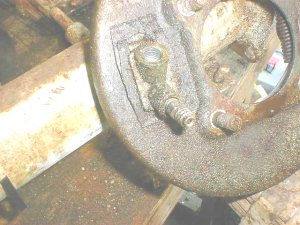 |
With the shoes out of position, the wheel cylinder can be taken off, two U shaped clips, one in from either side hold the cylinder in place. Once these have been taken out, the cylinder simply slips out. The cylinder will be left to soak in brake fluid to keep its seal lubricated, and then just before it gets re fiitted, I shall hone the cylinder to make sure its clean and ready for use. |
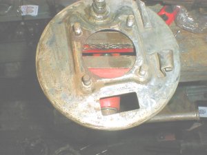 |
With the rear brake back plate void of all parts, this can now be cleaned and painted ready for the rebuild. I had thought of sending the plates to be galvenised, but seeing as they are both in excellent conditon after 40 years, I didnt think it was needed. |
 |
The rear axle was stripped back as far as possible, all bearings, seals, pinion and swivel gears where checked. only one bearing and all oil seals needed replacing. Painting was done by cheating, well in my books anyway, as luckily enough Hamerite produce a brush on paint in almost exatcly the shade I needed. Hamerite for those that dont know is a brush of paint, two versions can be brought. Hamerite as it suggests gives a "hammered" finish, while the product I used Smoothrite gives as it suggests, when applied correctly gives a smooth finish. |
 |
By laying the axle in position on its own with no brakes, wheels or suspension fitted, it is much easier to manouver it on your own and get the drive shaft somewhere near where you need it. At the engine end the centre axle that goes to the rear axle, fits inside a sleeve that comes of the rubber joint, then on to the engine. It is much easier to slide this in at the engine end first, then connect the drive rubber joints. |
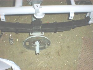 |
With some of the smaller parts refitted, I then began to refit some of the large parts that had been overhauld. The rear axle unit whilst not perfectly painted, was rebuilt with the leaf suspension ready to be hooked up to the main frame. This is just resting in position at present as the proper securing bolts are away at the platers being zince plated. I did this so I could begin to connect the brake hoses. My main worry was leaving all the brake parts dry for a long period of time allowing them to gunk or rust up. |
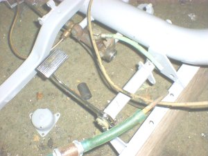 |
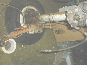
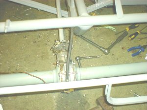
Time to get on with the brakes, I worked from the font back wards. The pedal has an outer and inner "tube". The inner tube is the axle to hold the outer tube on, the outer tube allows the pedal to rotate and pull the plunger on the master cylinder. The re chromed brake pedal sits on the toother part of the outer tube, and then is locked on by means of a bolt, exaclty the same as a kick start pedal. The brake line and fuel line was then fitted as this is proper brake line and is fairly un flexable. Fitting these first allowed me to put them in place without to much difficulty. |
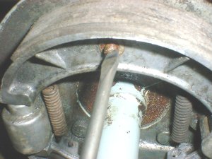 |
Unlike the two wheelers, there are two springs on the rear brakes shoes, as the wheel cyinders and a hand brake mechanism both expand the shoes. The front part of the shoes is the hydraulic foot brake, the rear shoes are operated by the hand brake, the handbrake is exaclty the same as a Lambretta drum, and cam twists and expands the shoes. The hydraulic brake part of the rear brake only pushes one shoe out, so I can envisage wearing one brake show out a lot quicker then the other! The pictures shoes the adjustment you need to make by means of a screw, this levels the shoes out, so they sit square in the drum, you might need one or two goes at this to get them spot on and working well. |
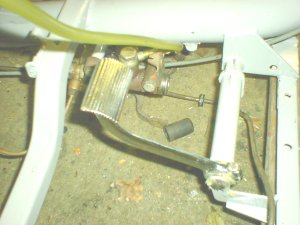 |
Connecting the master cylinder is pretty straight forward, on mine I have a remote resivior but in all the parts books I have it shoes a resivior built on top of the master cylinder. The foot pedal has an inner shaft that allows the outer shaft that takes the pedal, to rotate. It also has a welded on "holder" at the pedal end, so the inner shaft is held at both ends. You have to put the pedal on the outer shaft first, then thread the inner shaft through, at the frame end it is secured by a split pin, lining the hole up can take a couple of turns if you miss! |
 |
To aid in bleeding the brakes, I hooked the resivior on some welding rod and tied it to a screw in the wall, this allows gravity to help me bleed the brakes, plus it keeps it all away from the fresh paintwork as brake fluid and piant are not the best of friends. Unless you have a air feed brake bleeder, bleeding the brakes is a two person job. One pumps the pedal and keeps an eye on the fluid level making sure it does not run out, the other has to work at the wheel end. On the bleed valve on the wheel cylinder, you connect some hose, quarter fill a suitable container with fluid, and make sure the other end of the hose sits inside that fluid, that way you cannot get any air making its way back up the pipe. Keep pumping the pedal with the valve undo until you are happy no more air is coming out, once you are happy with this, the wheel man tightens the bleed valve on a downwards push of the pedal to ensure all air is out. |
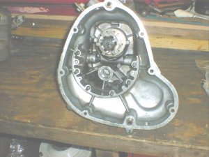 |
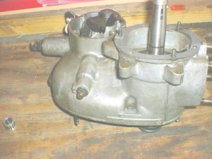
With the engine stripped out and cleaned, time for the rebuild. Taking apart and rebuilding the engine can be done in two main sections. The two halves of the casings seperate with mainly studs, but some bolt and nuts are thrown in for good measure! The first half is pretty straight forward Lambretta gearbox, four gears, a cluster, the gear selector etc. After checking all bearings, bearing tracks, and selector all seemed in pretty good condition considering the age of my Lambro. The gear selector as with all Lambrettas do tend to wear on the teeth that engage the gears. An Italian replacement (standard Lambretta item) was duly fitted with new spring, all bearings replaced for good measure and re fit the gears in the order I took them out. |
 |
If you get stuck re fitting the gearbox, in the homework manual it lists which way round to fit all the gears, it is the same in the Lambro box. I took mine out and laid them the way they would go back in, sat them on the shelf with all the other parts for safe keeping! With the gears all back in, ready to fit the end plate. New bearing fitted, and the end plate secures again as per Lambretta with a stud and nut arrangement, with two dowl pins for location. |
 |
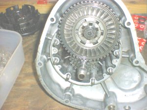
Luckily enough with the rear sprocket, clutch bell all in place, you can rig up a "bodge" job using a standard Lambretta clutch holding tool. I simply wedged one of my screw drives down one of the stud holes, lent the holder on it, wedge one of the legs of the holder on the bench, the other up against the screw driver. At first I gently applied the socket to start to tighten the clutch nut up. As the screw driver was so far down the hole, I could in fact apply all the pressure I needed to tighten the clutch nut up. |
 |
Having tried a two legged and a four legged standard Lambretta clutch compressor, niether of them worked. I took the casing into work so that I could try all of the other tools we have. The clutch was in the end compressed by using a J range rear hub puller as just about all the holes lined up. I ovaled two of the holes, and then used the clutch holder and two sockets carefully held in place to compress the clutch. Standard Surflex corks were used, with new Taffspeed clutch springs, and a set of new steels for good measure. |
 |
Unfortunalty we forgot to take photos of the crank removal, but if you have taken a crank out of a standard Lambretta there is not to much to worry about. The mag housing and stator are exactly the same as a two wheeled version, take the flywheel off using the proper holder and puller, undo the nuts and bolts securing the stator and housing. Use the two T bar extractors, or some long M6 bolts and the mag housing slipped out easily. Turn to the front sprocket size, apart from the front sprocket being very large compared to the Lambretta, every thing else is the same. Where the Lambro does differ is the drive side bearing. The bearing is accessed from the sprocket side, and is held in position by a "drive plate". This is a fairly similar arrangement to the normal Lambretta, but just backwards. Drive plate is secure on by four bolts, then the bearing and seal. Refit new seal and bearings, and replace the front sprocket assembly. |
 |
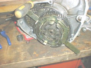
This pictures shows the new GP type crank fitted, at the rear is the kick start mechanism. This is probably a lot better idea in the Lambro then on the two wheeled scooters. The kick start parts are accessed by a cover, once the four bolts are taken out, the two pinions are accessable. These two gears look so solid and so well made, I doubt you would ever need to change them. One bolt holds each pinion in place should you ever need to , plus there is a rubber buffer that acts as a stop. After a quick inspection, all was well so it was decided not to take any thing out as it was needed to do a thing in here. |
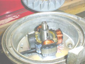 |
Re assembly of the seals, spacers and bearings is exactly the same as a standard Lambretta mag housing, small seal, dished washer and bearing. I ommited to re fit the spacer ring as I have fitted a GP crank and corrisponding bearing so this is not needed. Re fit the last seal, then the circlip, and the mag is ready to re fit. While tapping the mag down with my rubber hammer, I rotated the crank to make sure the seals didint catch or try to peen over. Wih the mag housing in place, time to fit the toy! I have opted for a Varitronic igntion system on the Lambro, not because it is a performance machine, but because the varitronic is such good quality, and has a high power output for the lights and indicators. My Lambro could also end up being used as a service vehicle, so it can also cope with running power for my laptop. In theory with the lap top plugged in, I can alter the timing on the Varitronic whilst driving along! |
 |
Talking of the kck start cover, it may pay you to refit this before the mag housing, i didnt! Three of the screws go in perfectly, whilst the other needed to be done with a right angled screw driver, taking a bit more time. |
 |
While my old 175cc top end was nearly good enough to use, I opted for a little more power as the cylinder stud spacings are the same as a 200. I fitted an Indian sourced cylinder and piston, pretty much standard straight out the box, but the better portng and 25cc extra shoudl give the little truck a bit extra. I will at a later date fit an alloy cylinder kit, but funds at present needs to me save all my pennies for more pressing jobs needed to be done! |
 |
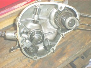
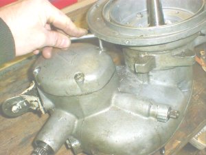
The engine is complete now, top end on, squish clearence checked and set, all the electrics fitted, the cowls and adjusters just need to be fitted and then the engine can be sat on its new engine mount rubbers and on the frame. Almost all other things need to be fitted to the cab, so at present I am stuck as this is still with the painters! |
 |
The rebuild begins, well on the parts I have back that have been painted or chromed. The main frame was powder coated, as to spray this would have meant a lot of overspray and wasted paint. Plus powder coating when done properly, is very durable, if done in a semi or full gloss can look quite good. Powder coating cannot be done where filler is needed, unless you lead fill. Rubbers that were recovered and restored to good enough condition have also been bolted on, these were the bump stops for the rear suspension and the seat rest rubbers. |
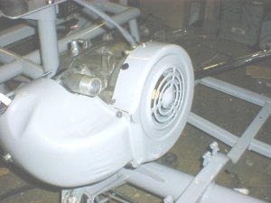 |
With the engine pretty much complete the freshly painted cowls were fitted, and the engine put in position. I have fitted a 22mm inlet manifold as I intend to use a 22mm Dell'Orto SH series carb if I can get the Lambro carb hose to work with it. If I can't, I will revert to the MA series carb originally fitted, as I have brought a new carb hose for it, and want it to retain the drain system. I could use a solid type GP or LD carb hose turned on its side, but these do not come with the drain system if fuel overflows or spits back. |
 |
On the left hand side you can see the two engine mounts, stub arms are bolted on the engine which extend to the mounts. The mounts are infact just rubbers with holes in them, the engine sits on top of these rubbers, a further rubber is put on top, and then caps bolted down to cap them off and secure the top rubbers. |
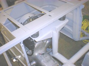
| I popped the seat frame on quickly to make sure the CDI and other parts would not foul the frame. |
| |
 |
 |
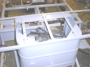
Taking pictures in the dark and using a graphics program to lighten them makes this shot look like the Lambro has been painted in different shades!
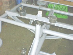
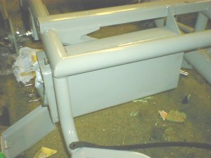
This picture simpy shows the tool box bolted in position, the rear of the box has two bolts/studs welded in position, the front part uses two bolts fitted upside down, with nuts and washers of course. |
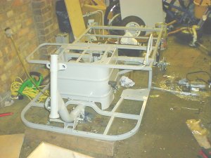 |
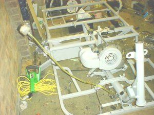
This is where my Lambro is as of 24/05/04. Brakes bleed and working, although one nut has split on the rubber hoese over the axle, so I will have to relace that and start the hole bleeding sarga again. Engine fitted on new mounts, rear axle, centre drive shaft, rear brakes, tool box, master cylinder and foot pedal all fitted. There is not much else I can get on with at present as the cab is still waiting for th painters to fit it in. I wish I had sent every thing for painting in one go, but half was done in powder coat, the wet paint my painters are just to busy! I hope to have this done by christmas, so I can begin the rebuld in the new year. |
| |
|